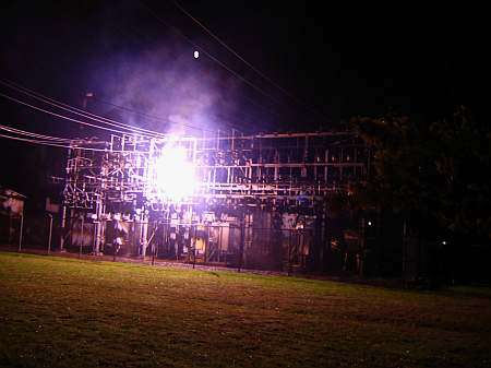
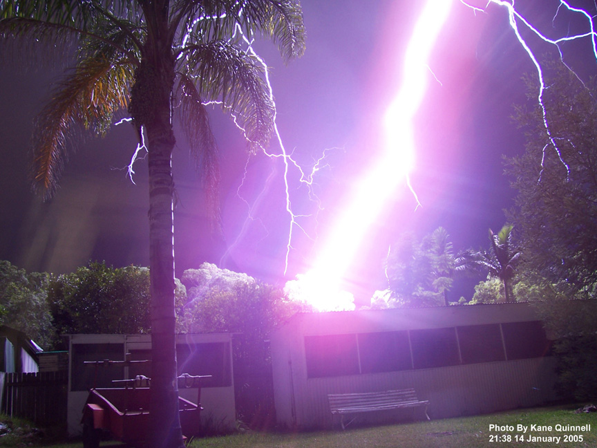
More Arcs 'n Sparks!

(Updated 12/19/22)


A 150 Meter (492 foot) Man-made Spark...

long spark!
The cylindrical object on the left houses a multi-million volt (MV) high voltage impulse generator, called a Marx Generator, at the Siberian Power Research Institute high voltage testing facility in Novosibirsk, Siberia. The positive polarity and rate of rise of the voltage pulse from the Marx Generator maximized the "efficiency" of creating long sparks. Although first reports of huge 100+ meter sparks were initially met with skepticism by scientists and high voltage engineers, a number of power engineers and scientists have subsequently witnessed similar events at this facility. Sometimes these errant bolts hit the top of street lamps in the adjacent parking lot!  At this facility, sparks up to 200 meters long have been created using a comparatively low potential of 5.2 MV. In order to gain a feel for scale in the above photo, the cylindrical building is 28 meters (~92 feet) high, and it houses a 28-stage Marx generator that's capable of generating positive or negative output pulses of up to 7 million volts. The building is constructed of closed-cell polyurethane foam, about 1 meter thick to withstand the high voltage stress.

In late 2005, a member of the Tesla Coil Mailing List (Dmitry, a Tesla Coiling enthusiast who lives near the facility) was able to schedule a visit with members of their staff. Dmitry subsequently shared details about this facility in a series of email messages to the other members on the list, and the excellent pictures he took can be seen on our mirror of Terry Fritz's old Hot-Streamer web site
A video slide show of this facility can be also be seen on YouTube. Through his efforts, we now know that the SIBNIIE generator uses 896 energy storage capacitors, each rated at 175 nF @ 125 kV. Each stage of the Marx uses thirty two capacitors to create an equivalent stage capacitance of 1400 nF at 500 kVDC. However, in order to prolong capacitor life, each stage is limited to 50% of this, or a maximum of 250 kV. The fully charged "erected capacitance" is ~50 nF and, at maximum output, the generator develops 1.225 million Joules (MJ) per shot.  In the above discharge, the maximum voltage was approximately five million volts, resulting in a point to point discharge of ~70 meters (230 feet). The estimated actual spark channel distance was ~150 meters (~492 feet). The pulse rise time was ~150 usec, duration was ~10 milliseconds, and the overall Marx bank energy was ~678 kilojoules.

An even larger Marx generator resides at the High Voltage Research Center (HVRC) in Istra, Russia. The facility was designed and built by the former German firm TuR, and was commissioned by Siemens. The facility is also the home of the world's largest AC Test Facility, with cascaded transformers capable of delivering 3 million volts AC at 12 million volt-amperes (MVA). The huge Istra Marx generator towers 43 meters (141 feet) high, and consists of fifteen stages. Each stage is capable of operating at a maximum of 600 kV. Each stage has a huge external voltage-grading ring to help equalize the voltage stress across the tower and to prevent unwanted corona or flashovers. The Istra facility is designed to generate a maximum of 9 million volts at an erect capacitance of 150 nF.  It is normally operated at a maximum of 6 million volts (~1.3 megajoules per shot) in order to prolong capacitor life. The following images show a daytime view of the Istra generator, and a man-made lightning bolt at night. Two incomplete leaders can also be seen issuing from the top toroid. Another unexpected branched leader can also be seen coming from the lower 12th stage grading ring. This generator has produced open air sparks as long as 150 meters (492 feet)!

July 2021 update:
Unfortunately, the Istra facility has been demolished to permit construction of a shopping center. The facility was last energized in 2014, and had become heavily overgrown with weeds and small trees and was in a marked state of disrepair. All that is left are the images and a few technical papers...

Istra 9 MV Marx GeneratorHVRC-Istra, Russia

Through high-voltage research at facilities such as these, it has been determined that switching surges on Extra High Voltage (EHV) electrical power transmission systems can initiate conductive plasma channels, called streamers, which can quickly lead to flashovers to other phases or ground, causing disruptive circuit breaker trips and unplanned service outages. The formation and growth of positive streamers may be a limiting factor for practical EHV power transmission system design. This phenomenon may place an upper voltage limit for AC transmission of about 1.2 million volts. As of 2019, the highest operating AC transmission voltage was 1.15 million volts, used in the Powerline Ekibastuz–Kokshetau, a 696 kilometer, three-phase transmission line that connects hydro power generating plants in Western Siberia, through Kazakhstan, to Russia. A 1.1 MV transmission system is also operational in China. However, India plans to implement an experimental 1.2 MVAC transmission system at their UHVAC testing facility at Bina in Madhya Pradesh. The Power Grid Corporation of India (PGCIL) plans to apply experience gained from this test facility to convert a 400 km transmission line (connecting Wardha and Aurangabad) from 400 kV to 1.2 MV, increasing the capacity of these transmission lines from 400 MW to over 6,000 MW.   

 (Photos Courtesy of Bazelyan & Raizer, "Spark Discharge", CRC Press, 1997, and Vladimir S. Syssoev and Yuri V. Shcherbakov,
"Electrical Strength of Ultra-Long Air Gaps", International Conference on Lightning and Static Electricity, September 2001, Seattle, WA)


MPEG of a 230 kV and image of 115 kV Three-Phase Disconnect Switch Opening Hot!


345 kV Arcs   
Click on image for a 1.25 MB MPEG
I recently received new information regarding this video from Wally Groff, a Journeyman Operator at Bonneville Power Administration (BPA). This video was captured in 2002 at a BPA substation located at the Haskill tap of the Libby-Conkelley No.1 230 kV transmission line near Kalispell Montana by Wally's supervisor. It shows a three phase vertical break disconnect switch attempting to de-energize an unloaded 34 mile long section of transmission line. This switch was part of an experimental design and is no longer in service. Air break disconnect switches are not intended to actively switch load current. In the above clip, the arcing is due to the attempted interruption of comparatively low reactive (capacitive or "charging") currents drawn by the open transmission line. Even with reduced current, the disconnect switch was not always capable of opening the circuit. At the very end of the clip, a brief phase-to-phase power arc causes a short circuit, tripping upstream interrupters and finally extinguishing the arcs. 

Wally was also kind enough to provide the following image of another disconnect switch that failed to open properly. This was a 115 kV quick break disconnect that had exceeded it's switching capability while attempting to de-energize a 24 mile section of transmission line at a BPA facility near Tillamook, Oregon. At times the disconnect switch operated properly, but not this day.
As can be seen, one phase successfully disconnected, but the other two phases did not. Luckily the operator was able to re-close the disconnect before it relayed out.

115kV Disconnect Failure
Click for larger image


MPEG of a 500 kV disconnect switch, one phase opens hot!

500 kV Air Break switch
Click on image for a 1.5 MB MPEG
The world's largest unintentional Jacob's Ladder! 
This video clip was captured by Neil Brady, the maintenance foreman of the 500 kV Eldorado Substation near Boulder City, Nevada at the time of the event. It shows a three-phase motorized air break disconnector attempting to open a high voltage source from a large three-phase shunt line reactor. The line reactor is the huge gray transformer-like object behind the truck at the far right at the end of the clip.  Line reactors are large iron core coils (inductors) which are used to counteract the effects of line capacitance on long Extra High Voltage (EHV) transmission lines. Internally, this line reactor has three coils, one for each phase in the three-phase system. Each coil within the reactor can provide 33.3 Million Volt Amperes of compensating inductive reactance (MVAR) at 290 kV between each phase to ground. Since the power company had previously encountered difficulty interrupting one of the three phases when trying to disconnect this line reactor, the substation maintenance crew set up a special test so that they could videotape the switching event, and they also made arrangements to "kill" the experiment, if necessary, by manually tripping upstream circuit breakers.

This particular disconnector uses gas filled switching elements, called "gas puffer" interrupters (circuit breakers). These are located just to the right of the rotary air break switches. The actual switching elements of these interrupters are hidden inside the gray horizontal insulators (bushings). The switching elements are housed within sealed "bottles" filled with a special insulating gas (sulfur hexafluoride, or SF6) under high pressure. SF6 is essential to rapidly extinguish ("quench") the arc that's created when the high voltage circuit is broken. During normal operation, the switcher will first open the SF6 interrupters. This disconnects the HV circuit so that the air break switches can rotate to the "open" position with no current flowing. Once the air break switches are completely open, the SF6 interrupters then re-close. This sequence normally insures that the air break switches only operate while de-energized and arc-free.

Each gas puffer interrupter uses two SF6 bottles that are connected in series, since it takes two switches combined to withstand the high voltage stress. In this video, one bottle was defective and failed to open. This placed the entire voltage stress across the remaining good bottle. As the good bottle valiantly tried to open the inductive load, it created a high voltage surge that caused the bushing of the good interrupter to flash over. The initial flashover can be seen arcing across the horizontal interrupter bushing at the very beginning of the video clip. Since the affected phase remained energized (through the flashover arc), the air break switch begins to open while still energized. It continues arcing as the switch rotates 90 degrees to the fully open position.  Once the disconnector reaches the fully open position, the SF6 interrupters re-close. Although this extinguished the horizontal arc across the good interrupter's bushing,  the arc across the air break switch persists, continuing to grow and creating a potentially dangerous situation.

The arc stretches upward, driven by rising hot gases and writhing from small air currents and magnetic forces, until it easily exceeds 100 feet in length. Switching arcs usually terminate long before reaching this size as they typically flash over to an adjacent phase or to ground. Once this happens, the abnormal current will be detected, causing an upstream circuit breaker to trip, disconnecting the faulty circuit. A phase-to-phase (short-circuit) arc can be seen at the very end of the previous 230 kV air break switch video, just before the resulting short circuit trips upstream Oil Circuit Breakers (OCB). Since the 500 kV arc was in open air and was sufficiently removed from adjacent phases, it could have persisted for quite some time. To avoid risking further damage to their equipment, the utility's dispatcher manually commanded the upstream circuit breakers to open, abruptly extinguishing the arc.

After this event, it was determined that both SF6 switch bottles in the affected phase had sustained permanent damage. The bottles were sent back to the manufacturer for analysis to determine why the interrupter failed. Loss of pressurized SF6 gas inside one of the interrupter bottles was determined to be the root cause of the initial switching failure. When the SF6 became depleted, the internal arc (created when the breaker tried to open) could not be extinguished. The circuit remained connected, through the internal arc, triggering the fault and incredible display.

As impressive as this huge arc may be, the air break switch was NOT disconnecting a real load. This arc was "only" carrying the relatively low (about 100 amps) magnetizing current associated with the line reactor. The 94 mile long transmission line associated with the above circuit normally carries over 1,000 megawatts (MW) of power between Boulder City, Nevada (from the massive generators at Hoover Dam) to the Lugo substation near Los Angeles, California. A break under regular load conditions (~2,000 amps) would have created a MUCH hotter and extremely destructive arc. Imagine a fat, blindingly blue-white, 100 foot long welding arc that vaporizes the contacts on the air break switch and then works its way back along the feeders, melting and vaporizing them along the way.  Still
, you've got to admit that this "little" 33 MVAR  arc is certainly one awesome sight!


And, who says utility guys don't have any fun - just listen to one of the guys on the maintenance crew "whoop" at the end of the clip!


MPEG of an Arcing 138 kV Substation and Exploding Power Transformer!

Substation Transformer Explosion
Click on image for 5.1 MB MPEG
This was an electrical substation that stepped down high voltage (138,000 volts) from a transmission line down to a lower voltage (23,000 volts) for local distribution to a community. It was conveniently located adjacent to a golf course and residential housing. In this clip, a ground fault on a capacitor bank on the low voltage side of the substation creates an arcing fault that behaves like an uncontrollable welding torch from Hell, chewing up everything in its path. Normally, the abnormal current would be detected and power automatically removed almost immediately by substation protective hardware. Unfortunately, in this case, the protective hardware failed or was unable to sense the presence of the arcing fault. Excessive current eventually causes the windings on the substation's power transformer to overheat, severely cooking its innards and raising the flammable mineral oil within to the boiling point. In a vain attempt to prevent the transformer's tank from exploding, pressure release valves or a failing tank gasket vents steam-like clouds of superheated oil vapor. The foggy mist of hot oil is then ignited by the arc, causing it to explode in a ball of flame. This is quickly followed by a phase-to-phase short on the HV side, perhaps caused by a flashover within the flames or by a heat-induced fault within the transformer . The phase-to-phase short causes an upstream circuit breaker (in another, larger substation) to blow, finally killing power to this substation.

However, by this time, the overheated transformer's tank fails, and it dumps hundreds of gallons of flaming mineral oil onto the already devastated substation. Local firefighters can only watch from a distance since there's no way to safely fight this fire. The substation is a total loss. As linemen often say, "Firemen don't mess with their wires, and linemen don't mess with their fires".  A very sobering look at the explosive power lurking within that quietly humming substation in your neighborhood...

NOTE: Based on recent inputs from employees of Florida Power and Light, this event occurred at the Ives Dairy Substation located near San Simeon Way and Biscayne Boulevard in Miami, Florida. It is believed to have occurred in 2000 or 2001, and the footage was captured by a local resident from his home which was adjacent to the country club and golf course. The root cause was a defective fuse holder associated with motor-operated high voltage switches. Substation switch gear was disabled when a small fuse blew, opening control power for the substation's protection hardware. Normally, the blown fuse would trigger an alarm to the dispatcher and the problem would be promptly fixed by maintenance personnel. However, in this case, the defective fuse holder also prevented the alarm from being sent, so the power company was unaware that the substation had become completely unprotected.

Some time later, a low voltage side capacitor bank failed, creating an arcing fault that could no longer be cleared, since the substation's protection hardware was inoperable. The arcing fault ultimately led to the total destruction of the substation. Although at least one report indicated that the spray of white mist might have been water from a fire suppression system, it is now known that this particular substation did not employ an active fire suppression system. The spray was, in fact,  a "fog" of overheated, vaporized mineral oil, and the explosion was quite likely an example of a dangerous BLEVE (Boiling Liquid Expanding Vapor Explosion).

If you can provide any more information about this event or know who captured this footage, please contact us.


480 volt 3-phase Arc Flash Demonstration

480 volt arc flash demo
Click on image for a 30 second 4 MB clip

An electrical explosion, or "arc flash", occurs when one or more high current arcs are created between energized electrical conductors or between an energized conductor and neutral (ground).  Once initiated, the resulting arc(s) can bridge significant distances even though the voltage is relatively low. In the above demonstration, arcs were intentionally initiated by bridging #28 AWG wires across three bus bars in a testing laboratory. When power is applied, the wires immediately explode, forming a conductive plasma which evolve into high-current power arcs between the bus bars. In the above example, three one inch copper bus bars were separated by one inch, and were connected to a 480 volt open circuit source (a large delta-connected distribution transformer). During the 842 millisecond event, the average short circuit current was 17 kiloamperes, and the peak current exceeded 30 kiloamperes. The energy dissipated within a power arc is limited only by the fault current capability of the upstream power source and the duration before protective hardware "clears" (interrupts) the short circuit. In many low voltage (480 - 600 volt) electrical power distribution systems, fault currents can exceed 70,000 amps. The thermal energy liberated within these high-current arcs can be many tens of megawatts - equivalent to several sticks of dynamite. The arc core may reach 35,000 degrees F (four times the surface temperature of the sun!). As the arc "roots" vaporize portions of the copper bus bars, the copper vapor explosively expands to over 60,000 times its solid volume. The incandescent copper vapor rapidly combines with oxygen in the atmosphere, forming dense clouds of cupric oxide, blackening the air and covering nearby objects with black "soot". Globules of molten copper are also violently ejected, showering the immediate vicinity with 2,000+ degree droplets at speeds that can approach 700 miles per hour.

Magnetic forces also propel the arc along the bus, extending it in the process. The high currents also generate huge magnetic forces that can bend thick bus bars or even rip them from their mountings, possibly creating additional shrapnel.  Any unprotected individual unlucky enough to be anywhere near this event would be seriously injured or killed. Because of the extreme danger, most countries now require electrical workers to wear protective clothing and headgear whenever working near energized high-energy equipment. Some additional video clips that demonstrate the effects of 480 volt industrial arc flashes and their effects on manikins clothed in regular (unprotective) and protective clothing can be seen on the Westex site.

High Voltage Fuse Fails in a Substation, Continues Arcing...

Corvallis, OR arcing substation
Click on image for a 35 second video clip

The above incident was captured on October 30, 2005 at a Pacific Power substation in Corvallis, Oregon by nearby Oregon State University students. An overload on one of the phases apparently initially caused a HV fuse to open too slowly. High voltage fuses are normally designed to open quickly, either by rapidly generating large volumes of internal gas to explosively "blow out" the arc (as in an expulsion fuse),  or to vaporize a thin silver wire embedded within quartz sand, creating a high resistance "fulgurite" that quietly opens the circuit (as in a Current Limiting Fuse or CLF). In the case of this particular fault, a HV fuse opened but it failed to quench the arc, causing the circuit to remain energized through the resulting arc path. Although in the clip the arc is initially only passing load current, the arc eventually chews up the fuse body. The arc then jumps to other portions of the fuse holder or to the grounded substation support structure where it can inflict significant damage. As can be seen in the clip, the arcing ended up raining a bit of molten metal down to the substation floor before power was finally cut.
Used with permission by Douglas Van Bossuyt, douglas.vanbossuyt@gmail.com


Crane Tangles with a 46 kV Feeder... and Loses!

Crane1 Crane2a.jpg Crane3a.jpg Crane4a.jpg
Crane5.jpg Crane6a.jpg

The above sequence of images show what happens when the boom of a Link Belt crane accidentally comes too close to a 46 kV power feeder. The HV feeder arcs to the boom, elevating the potential of the entire crane to 46 kV. The base of the crane then arcs to the steel reinforcement bars in the concrete, vaporizing moisture in the concrete below the crane, causing it to explode! After a couple of re-closures, the feeder's cut-out (circuit breaker) finally locks out, killing power to the feeder. However, by this time the crane's hydraulic oil, hoses, and tires have all ignited, and the crane becomes a total loss, as it becomes fully engulfed in flames. Fortunately, the crane's operator escapes with only minor injuries.


Huge positive lightning bolt almost zaps an Australian lightning photographer

(Click on image for larger view (199 kB))
Nearby_Lightning_Bolt
Photo courtesy of Kane Quinnell

The above photo is courtesy of Kane Quinnell from Australia. It was almost his last. The above lightning stroke was almost certainly a "bolt from the blue" - a relatively rare positive lightning bolt that originates from the top region of a storm cloud rather than from the negatively charged cloud base. These massive discharges can travel horizontally, often in the clear air away from the storm, for up to 35 miles from the top of the main storm. Positive lightning bolts can pack peak currents of up to 340,000 amperes, and they usually have a long lasting "tail" of current that persists for hundreds of milliseconds. This is about ten times more current and ten times longer than regular (negative) lightning. As a result, positive lightning is extremely hot, and it does considerable damage to whatever it hits. If you happen to be unlucky enough to be the target of one of these monster bolts, you DO NOT survive. If you look at the above image very carefully, you can see a small leader coming up from the top of the shed, just to the right of the main stroke. Here's some additional information about "Bolts from the Blue", and following is Kane's description of what happened in his own words:

"I happened to be out in the back yard, watching a storm on Friday night (14/01/05) that appeared to be a few km away, (I live in Old Toongabbie, and the storm appeared to be in Pendle Hill, or Greystanes, Australia). I set the camera's settings so that the shutter remained open for four seconds, placed it on the back bumper of my car, hoping to get a few shots of lightning in the clouds a few kilometers away. There was no rain at all, and stars could be seen over the north 1/3 of the sky, so I did not feel in danger in any way. Boy was I mistaken... DO NOT UNDERESTIMATE ELECTRICAL STORMS - YOU COULD GET YOURSELF KILLED!

I clicked away a few times, and got nothing, and then clicked the button again, and within 0.5 seconds of me pressing the button, I had jumped at least 2 metres in the air, as I heard a tremendously loud crack of thunder, and see this amazingly bright beam of electricity right in front of me. I had then landed, grabbed the camera, and was inside the house within 2 seconds.

I did not realize just how lucky I was until I uploaded the picture to my computer, and saw a leader stroke that must have originated no more than 2 metres from where I was standing next to my car, under my carport. Had the main charge taken the leader near me, rather than the one it did, I would be dead.

When lightning strikes, it actually comes up from the ground first (called a leader stroke), this stroke makes the air within it conductive, and once it reaches the cloud, you have a complete circuit, and the bolt of lightning comes down from the cloud along the leader stroke. First leader to the cloud wins, luckily mine did not.

I estimate that the main bolt was approximately 1.5- 2 metres in diameter, and struck something in the yard behind the shed that is located at the back of the yard. That would have had an extremely large charge, and would have been extremely hot, hotter than the surface of the sun, at 5,500 degrees Celsius, it could have been around 30,000 degrees Celsius. Needless to say, I was buzzing for the rest of Friday night, due to the amount of adrenaline going through me 'cause of how close it had come."

Kane Quinnell was one very lucky bloke!


NEW! Dueling Musical Tesla Coils Zap a Daring Chicago-area Tesla Coiler

This was captured on September 8, 2007 in Baraboo Wisconsin at the 2007 Cheesehead Teslathon, sponsored by Resonance Research Corp. Local coiler "Dr. Zeus" (Terry Blake) challenges man-made lightning bolts from two identical high power solid state Tesla Coils. The Tesla coils, constructed by Chicago-area coilers Steve Ward and Jeff Larson, are being modulated via separate MIDI outputs from a laptop PC. Steve Ward's coil is on the left, and Jeff's coil is on the right. Each coil is capable of generating sparks over 10 feet long. Dr. Zeus is wearing a custom-designed personal metallic "Faraday Cage" that fully protects him from the high voltage current. He easily lights a string of 120 volt light bulbs from the high current coming from Steve's coil, takes simultaneous hits from both coils, and when he steps onto a 1/4" polyethylene sheet, you can see sparks jumping off his feet to ground. Stay tuned for even more incredible footage on YouTube...
WARNING: This is an EXTREMELY dangerous demonstration that requires extensive high voltage
experience and electrical engineering expertise. It should NOT be attempted by amateurs!! 


2.2 Million Volt miniature lightning bolt discharges inside a acrylic block...

(Click on image for larger view)
12" x 12" specimen being discharged
Photo: Courtesy Terry Blake

A miniature "lightning bolt" forces its way out of a highly charged 12" x 12" x 1" sheet of acrylic. A 5 million electron volt (MeV) linear accelerator was used to force trillions of high-energy electrons deep inside the block. This created a highly charged, cloud-like region of electrical charge, called a space charge, about 1/2" below the top surface of the specimen. Since acrylic is an excellent electrical insulator, the huge charge became trapped, similar to the way electrically charged regions are temporarily trapped within thunderclouds prior to a lightning strike.

The space charge region reached a potential of over 2.2 million volts prior to being discharged. We then manually created a path for the trapped charge to escape by carefully poking it with a pointed grounded conductor (as shown above). This allowed the trapped charge to overcome the electrical strength of the acrylic, creating thousands of white-hot, ionized (electrically conducting) paths, and permitting the trapped electrons to rapidly escape through the main "root" of the discharge. Note that excess charge is actually being REMOVED from the specimen, not being injecting into it.  The following video clip shows a cube that was previously charged along six internal planes being manually discharged, followed by a series of secondary discharges. Larger specimens may sparkle and sizzle for up to tens of minutes after the main discharge.

Lichtenberg Cube Discharge
Video courtesy of Theodore Gray

As the electrons surge out of the block, they create a brilliant, high current, lightning-like discharge that lasts for only 40-80 billionths of a second (40-80 ns).  The peak current in the above discharge (taken through a dark filter to reduce its brilliance) is estimated at over 500 amperes. A larger specimen, such as the 12" specimen above, may have discharge currents of several thousands of amperes. The energetic electrical discharges create millions of permanent microscopic fractures arranged in tree-like branching chains. The characteristic fractal pattern that's left behind is called a Lichtenberg figure - or what we call a "Captured Lightning" sculpture. A video showing how we make these can be seen here.

(Click on image for larger view)
4" square Lichtenberg Figure

A charged piece of acrylic behaves like a charged high-voltage capacitor. When injected with trillions of extra electrons from a particle accelerator, a harmless-looking slab of acrylic can store a surprising amount of electrostatic energy. For example, the charged region within a 12"x 12" x 1" specimen can store almost 1000 Joules (watt-seconds) of electrostatic energy - about 3X the maximum energy used in a heart defibrillator.  Discharging large Lichtenberg figures must be done carefully, since the high current discharge could potentially injure, or even kill, an unwary experimenter.  Because of their intricate detail and beauty, Captured Lightning sculptures bridge the boundary between art and science. The chains of tiny fractures behave as microscopic mirrors, reflecting ambient light, and brilliantly glowing when illuminated through the edges. Considerably more information about these fascinating scientific sculptures can be found here. Stoneridge Engineering LLC is proud to be the premiere source for the world's most beautiful 2D and 3D Lichtenberg figures. Be sure to visit Gallery1, Gallery2, and Special Lichtenbergs to view some of our best work.


Huge 15" x 20" x 2" Lichtenberg figure being created (2.5 million volt discharge):
(Shows unloading after irradiation, main discharge and secondary discharges)


What Happens when a LIVE High Voltage Power Line Hits the Ground?

The following pictures are of a man-made fulgurite that was created when a high voltage power line fell during a windstorm, and then continued to arc to the ground for a couple of hours. When a high voltage power line initially contacts the ground, it begins arcing. The intense heat of the arc and the high current flowing into the ground cause sand, rocks, and minerals in the soil near the line to fuse into a glassy, lava-like substance. A couple of video clips showing downed power lines arcing to the ground can be seen here and here. In the latter video clip, the molten region of soil near the downed line can clearly be seen glowing for quite some time even after power was turned off. For a variety of technical reasons, downed power lines may remain energized for quite some time before the power company detects the problem and kills power to the circuit. Even worse, automatic "re-closers" may temporarily cut off power for a few seconds, and then reapply it with no warning. This sequence may repeat several times before the re-closer locks out and must be manually reset. During the brief dead times, people nearby may think that the line is safely dead,  and may get injured or killed when power is suddenly reapplied.

Since molten minerals are excellent electrical conductors, the current-conducting area around the line continues to expand and glow as electrical power continues to flow into the ground fault.  Once power is finally removed, the molten materials solidify into a bubbly, glassy "rock", leaving a man-made "fulgurite" behind. Unlike natural fulgurites, those created by a downed power lines tend to be considerably thicker and more massive. Linemen sometimes call these curious artifacts "clinkers" because of the ringing sound they make when struck or because they resemble the ash left over from burning coal (also called clinkers).  As with natural fulgurites, clinkers are often hollow with polished, glassy interior walls. However, because they're thicker, they tend to be considerably heavier and massive than the thin, fragile lightning-created fulgurites which are created within a fraction of a second.

Clinker1Clinker2
Clinker3

These  pictures are of a clinker that was formed in Northern California in 1994 when a 7,200 volt power line fell onto a pile of clam shells next to a canal in Hickman, California.  Although this 28 inch long specimen weighs about 80 pounds, it is actually only a small piece of the 15 foot long clinker that was created during the fault. Shell fragments can be seen embedded in the exterior of the glassy walls.  The above pictures were provided courtesy of  Scott Falke. This specimen currently resides in the Turlock (California) Irrigation District's corporate office.

Physics is fun!


Some other interesting places to visit:
Tesla Information Center
Tesla Coil
Quarter Shrinking Page
Shrunken Coins for Sale
Lichtenbergs for Sale
Tesla Info Center
10" Tesla Coil
The "Quarter Shrinker"
Our Shrunken Coins
Our Lichtenberg figures

 
Go to Stoneridge Engineering LLC Home

Extreme Tracker
Copyrighted 1999-2021. All rights reserved.  No portion of this page may be reproduced without written consent from the author.